 |
| November 26, 2013 | Volume 09 Issue 44 |
Designfax weekly eMagazine

Archives
Partners
Manufacturing Center
Product Spotlight
Modern Applications News
Metalworking Ideas For
Today's Job Shops
Tooling and Production
Strategies for large
metalworking plants
Engineer's Toolbox:
6 ways to optimize your pneumatics
Bosch Rexroth experts air their concerns and solutions.
The push to achieve reductions in energy consumption is a significant global trend. Many companies have begun offering incentives to employees to reduce costs and achieve higher energy efficiency. In some regions of the United States, companies can profit from rebates given by electric power suppliers for reductions in compressed air usage.
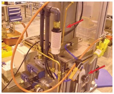
When generating and using compressed air in industrial machines, targeted measures within a comprehensive energy-saving concept can significantly improve energy efficiency at the machine level. In the application above, an in-line pressure regulator with reverse flow was installed to reduce pressure on the non-load stroke, resulting in a 38 percent reduction in air consumption for the press operation.
Machine builders aiming to improve the energy efficiency of their machines tend to focus on using energy media other than pneumatics (typically electro-mechanical or hydraulic), since pneumatics, as traditionally applied, is viewed as inefficient due to factors like leakage and over-pressurization (i.e., supplying a higher pressure in an actuator to accomplish a task which is endemic in practice).
But they shouldn't.
When generating and using compressed air, it's true that there are many places in the system where energy can be lost. However, targeted measures within a comprehensive energy-saving concept can prevent these losses and significantly reduce energy consumption at the machine level.
Consider the following tactics to avoid dead volumes and optimize the use of compressed air:
1. Bigger isn't always better
On new machine applications, correct component dimensions are a great start to obtain optimal energy usage. With pneumatic components, bigger doesn't mean better when over-dimensioning leads to unnecessarily high air consumption. It is common practice to assume "when in doubt, go one size bigger," or to re-use designs that were selected and worked on previous projects even though they may be overkill in terms of space and weight on the machine. This causes avoidably high air consumption and costs more to purchase and operate.
Reducing cylinder diameters helps to save air volume. The use of online configuration tools, calculation programs, and energy-saving calculators helps determine what component dimensions are needed for the application.
In one lumber industry application, a sawmill machine's output increased 13 percent by simply reducing the size of the pneumatics used on the sorter gates of the machine. The cylinder bore was reduced from 3 1/2 in. to 2 in., 1/2-in. air valves were reduced to 1/4 in., and pressure was reduced from 100 psi to 60 psi. With these seemingly minor alterations, the company effectively increased its production speed and achieved energy savings of 75 percent on the machine.
What about OEMs that build standard machines and sell to a variety of end-users? In order to mass produce a standard machine, it needs to be designed and sized to accommodate the end-user with the lowest available pressure. This usually means specifying larger, more expensive components, resulting in increased air consumption. This issue can partially be solved by ensuring that the supply pressure to the machine is regulated down to the design pressure level. It is common for operators to increase supply pressure on regulators in the hope of improving performance, but this ends up costing the end-user significant amounts of money in operating costs for no actual benefit if the components were sized correctly. It is important to monitor machine system pressure to ensure that it is within both a minimum and a maximum value to avoid energy waste.
2. Apply pressure regulators to cylinders with no-stroke loads
Best practices of lean manufacturing call for the elimination of any waste that does not add value to the product or process at hand. With pneumatics, energy is frequently wasted in this manner when too much pressure is applied for tasks that do not require that equivalent level of force. This can be overcome by using pressure regulators in pneumatic cylinders to control exactly when to exert energy and when to conserve it. By applying the exact amount of pressure needed for each task, machines can realize energy savings of up to 40 percent in many cases. It is important to note that pressure regulators installed between a valve and cylinder are capable of operating with "reverse flow" and they are becoming increasingly common and lower in cost -- usually much more economical and easier to install than traditional sandwich pressure regulators. Many standard in-line pressure regulators do not have this functionality, and in such cases a check valve is required in parallel to accommodate the reverse flow.
In many applications, there is either a "push" or "pull" load, but not both. Most often, the same pressure is used for both the "push" and "pull" strokes, which is extremely inefficient.
In one application example, a pneumatic cylinder was being used in a press-fit operation to perform an assembly task. The cylinder required 100 psi pressure to perform the press operation, and 100 psi was also applied to the retract. However, the retract function only required <10 psi pressure to accomplish the same task. By adding a pressure regulator between the valve and cylinder port, the retract pressure was reduced to 10 psi -- a 90 percent reduction -- resulting in a significant drop in energy consumption for the press-fit operation. In total, the machine attained 38 percent energy savings per cycle, and ROI of the components is approximately 2,100 cycles.
Typical machine tasks that could benefit significantly from non-load stroke pressure regulation include press-fit processes and applications that utilize rodless cylinders or lifting cylinders, such as automotive assembly elevators. In general, the larger the cylinder, the larger the efficiency gain, and the key characteristic to be on the lookout for is where there is a sizable difference in the force required for each stroke direction.
Energy savings is just one of several benefits of applying pneumatic pressure regulation. Since piston speed is governed by the rate at which the air on the non-load side of the piston is exhausted, reducing the non-load pressure of the cylinder enables faster piston speed on the working stroke, decreasing cycle time. Other advantages include reductions in shock, vibration, and noise as well as longer life expectancy for the components and the machine itself. If there is leakage in the system, its cost is inherently reduced by reducing the air pressure at the leakage point.
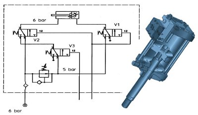
Regenerative valve circuits (like the one from Bosch Rexroth pictured at right) divert air being exhausted from the cylinder stroke and use it to charge the opposite end of the same cylinder when out-stroking.
3. Consider regenerative circuits
For some applications that require pressure for a load in both the "push" and "pull" stroke directions, the implementation of a regenerative air-savings system can produce an air savings of up to 50 percent. Rather than installing a pressure regulator to cut air consumption (such as in the previous example), instead the air in the load side of the cylinder is recirculated back into the other side of the cylinder to do work.
An example of where this can be applied is on crust breaking in aluminum processing. Large cylinders are mounted vertically with the rods facing down. Due to the weight of the tooling, high air pressure is required to retract the cylinder rods. High pressure is also required to extend the cylinders even though they are assisted by gravity. The high pressure is needed toward the end of their stroke to create a force to break a crust. The same characteristics apply in some clamping applications where the high force is only required toward the end of the working stroke. Regenerative valve circuits divert air being exhausted from the cylinder stroke that has gravity assist, and the technology is used to charge the opposite end of the same cylinder when out-stroking.
4. Optimize vacuum applications
Machine applications that use vacuum generators (or ejectors) typically consume much more energy than is necessary to perform the material handling task at hand. In conventional systems, vacuum generators are energized by a solenoid valve that supplies compressed air, and vacuum cups of various profiles and materials come into contact with the product itself. As long as vacuum force is applied to hold the component at the vacuum cup, air is being consumed by the vacuum generator. Since vacuum cups are prone to wear over time, vacuum generators tend to be oversized to accommodate this and therefore consume a higher amount of compressed air, leading to increased operating cost of the equipment and greater noise in the machine.
To remedy this, consider retrofitting the machine with a vacuum generator that has an automatic air-savings option. Vacuum generators with air savings, such as the ECS series from Bosch Rexroth, monitor vacuum levels with an integrated sensor. Once the generator is switched on, the vacuum valve remains active only until the preset vacuum value is reached. As long as the vacuum value lies within the programmable hysteresis range, the valve automatically de-energizes and remains closed, consuming no compressed air. If the vacuum drops below the preset limit value (due to a leak or other disruption), the solenoid valve is energized again until the preset vacuum value is reached.
Optimizing vacuum applications with air-savings control can greatly reduce air consumption and operating cost. Vacuum generators with air-saving functions can be easily installed or retrofitted to improve efficiency. Other tangible benefits include significant noise reduction on equipment due to increased off-time of the vacuum valve. Furthermore, the frequency of vacuum sensor activation can be used as an indicator of both wear and overall efficiency of the system.
5. Minimize leaks, control "off-duty" air pressure
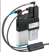
Look for vacuum generators with air-savings options like integrated sensors to monitor vacuum levels.
Leaks are costly. For end-users seeking to improve the efficiency of the pneumatics on their machines, the low-hanging fruit is finding and fixing leaks.
Leakage can commonly be attributed to factors such as valve design and the deterioration of seals. Some valve designs, such as lapped spool valves with metal sealing, have inherent internal leakage up to 700 cc/min even when brand new. The leak is constant as long as there is air supplied to the valve. Switching to comparable valves with soft seals instead of metal seals can cut the allowable leak limit to between 10 cc/min and 30 cc/min.
Leakage can also be caused by chemicals in the air system that are incompatible with industrial elastometric seals. The first component to fail due to incompatible chemicals in the air supply is the pressure regulator. If deterioration of elastometric Buna seals occurs, consider installing an active carbon filter bed or lubricator, or switching to devices with non-Buna seals such as HNBR, Viton, Teflon, hard sealing (e.g., ceramic), or polyurethane.

Special polymers allow for smaller, lighter, chemical-resistant valves (like the LS04 valve from Bosch Rexroth) that can be mounted right next to the actuator.
The implementation of automatic air-reduction control is another means of significantly increasing machine efficiency. Most existing machine installations have no automatic means of shutting off air to machines when not in use, and having maintenance personnel individually turn off air to specific machines is too cumbersome. Some machines may require pressure for certain functions to be supplied even after the machine is turned off and there is no production (examples include air bearings, air gauging, and cleaning). Frequently, however, these functions can be satisfied with greatly reduced supply pressure or with pressure for a limited time period. If a plant has two shifts/five days a week, an automatic air-reduction control package can be added to automatically reduce the supply pressure during the hours that the plant is not in operation. In the event that higher pressure is required during off-hours, the system can be overridden.
6. Decentralize the valving
Centralized valve manifolds not only have the reputation of being cumbersome and using long air lines, they also consume a lot of energy. Small, decentralized valve units with competence and intelligence at the site of the application offer greater efficiency. The concentration of pneumatic functions prevents pressure losses through long lines from the control cabinet to the pneumatic drive. Tubing connections can be significantly reduced (by 50 percent) by using valve/actuator units, resulting in an energy savings of 35 percent.
Manufacturers of pneumatic components now offer smaller, lighter, chemical-resistant valves -- thanks to special polymers -- that can be mounted right next to the actuator. This direct connection of valves and cylinders eliminates pressure losses, which arise from long connection lines. Decentralization of the system can also yield faster response times and higher cycle frequencies.

Rexroth Series CL03 Clean Line valves (available with serial link) withstand high-pressure wash-down, allowing the valve manifolds to be located closer to the application to reduce air consumption and eliminate the need for a protective cabinet.
Modern valves and manifolds are available with IP69K (high-pressure wash-down) protection and sanitary design with materials that are suitable for food processing. This eliminates the need for the traditional locating of pneumatic valves in remote stainless steel enclosures with long tubes in between. The energy savings is gained by the elimination of over 50 percent of the tubes and improved response time due to the valve being located where the actual work is being done.
The bottom line
On a plant-wide level, steps to achieve greater energy efficiency can certainly be implemented, but end-users should work with their OEMs to consider what steps can be taken at the machine level. Energy costs comprise more than half the total cost of ownership in pneumatics today, and a constructive evaluation of pneumatic applications will quickly pay off. Every application is different, and the overall machine concept and types of components used influence the potential for energy savings. Pneumatics should be considered in the strategy to achieve greater energy efficiency in industrial machinery.
Source: Bosch Rexroth
Published November 2013
Rate this article
View our terms of use and privacy policy